Introduction
You receive an offer for a BESS container: 5 MW / 10 MWh. Price: around €2 million. Do you sign?
Before you do, you should know what you’re actually buying. Because “a container with batteries” is an oversimplification that can cost you a fortune.
From the outside, it’s just a regular container. Inside — a small power plant. Theoretically, everyone sells the same product, but that’s only an illusion. Choosing the right equipment can save you many problems down the road. And if only CAPEX matters — it’s worth knowing what you can skip and what you absolutely cannot.
Lesson from practice: If anyone has ever bought something from China, they know perfectly well that you get exactly what you ordered. If it’s supposed to be a “battery container” — that’s exactly what you’ll get. Read: container + cells = nothing more, nothing less.
I witnessed such a situation. The order said: “container with battery cells.” And that’s exactly what arrived. You can’t argue with the supplier’s logic — we got what we ordered. The problem was that it wasn’t a complete energy storage system.
It’s best to learn from others’ mistakes. In this article, we’ll break down a BESS container into its components and show you what questions to ask your supplier before signing the contract.
Component Hierarchy: From Cell to System
An energy storage system is not one large battery — it’s a precisely organized structure consisting of thousands of smaller elements. Cells are in modules, modules are in racks, racks in strings, and strings make up the entire container.
Cell
The basic building block. For LFP (lithium iron phosphate) technology, which dominates the utility-scale market, we’re talking about prismatic cells with a voltage of 3.2V and capacity of 280-314 Ah.
A single cell weighs about 5-6 kg and is roughly the size of a small brick. In a 5 MWh container, you’ll find several thousand of them.
Why LFP? Because it’s more thermally stable and usually better suited for long cyclic operation. In practice: lower risk, greater resistance to weather conditions — meaning temperature and work intensity.
What to look for:
- Cell manufacturer (there are several)
- Certifications (UL1642, IEC62619)
- Degradation warranty (typically 60-70% capacity after 15 years)
Module
Modules are created by connecting cells in series — usually 8 to 16 units. A BMU (Battery Monitoring Unit) is added to each module, monitoring the voltage and temperature of each cell.
A typical module has a voltage of 50-60V and a capacity of several kWh. This is the basic service unit — in case of failure, you replace the module, not individual cells.
Rack (Battery Cabinet)
A rack is a vertical cabinet containing several to a dozen modules connected in series. Typical rack voltage is 600-1500V DC.
Each rack has its own Rack BMS (RBMS or SBMS — String BMS), which aggregates data from modules and communicates with the higher-level management system.
In a rack, you’ll also find:
- DC disconnect with lockout capability
- Overcurrent protection
- Communication interface
Container (System)
A 20-foot container (ISO standard) typically contains:
- 8-12 battery racks
- Top-level BMS system (Master BMS)
- Thermal management system (HVAC or liquid cooling)
- Fire safety system
- DC distribution board
- System controller
- Communication interfaces (to PCS and SCADA)
Important: Modern 5 MWh containers use 314 Ah cells, allowing 45% more energy to fit in the same space compared to the previous generation (280 Ah cells).

BMS: The System’s Brain (That “Limits” the Battery)
BMS (Battery Management System) is one of the most important elements of an energy storage system. And simultaneously one of the most misunderstood.
What is BMS?
BMS monitors battery safety: voltages, temperatures, currents, balancing. And makes decisions: whether to charge, discharge, or whether to limit power or disconnect the system. BMS is the guardian of your investment.
Additionally, you usually have a higher-level controller that connects it with EMS, the optimizer, the energy market, or the facility’s profile.
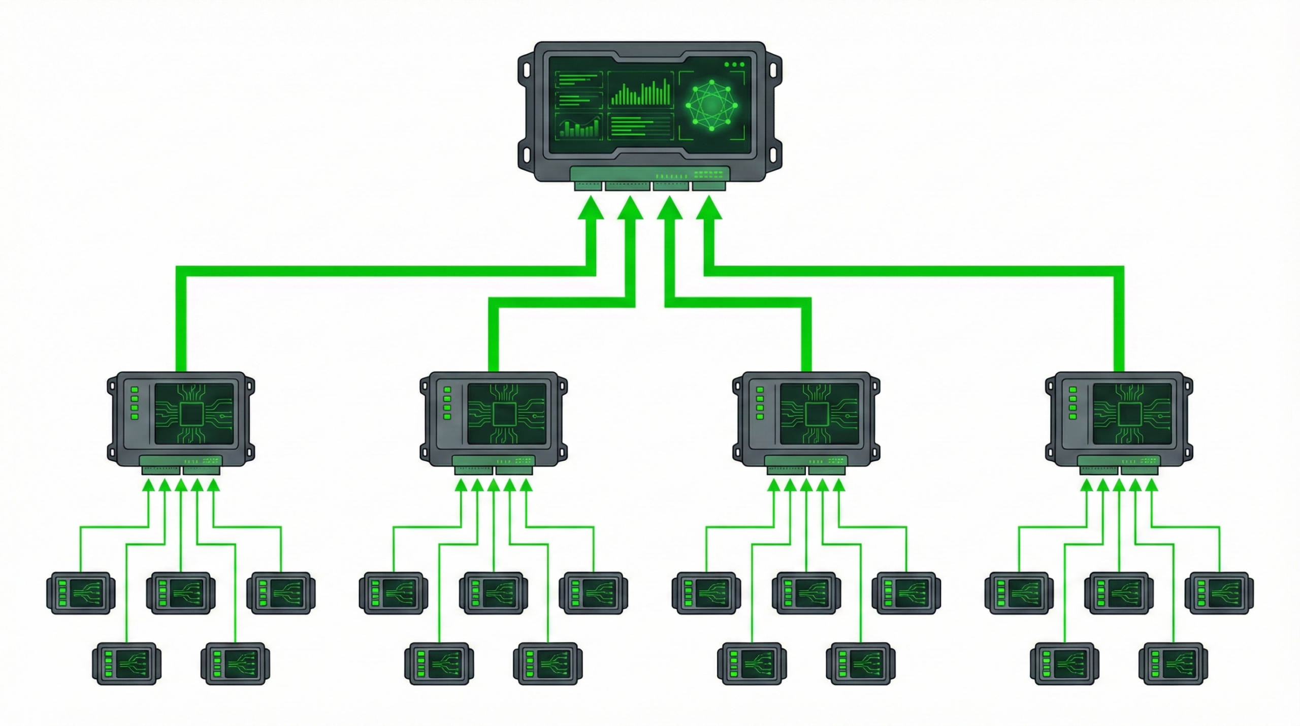
Three Levels of BMS
- BMU (Battery Monitoring Unit) — module level
- Monitors individual cells
- Performs passive or active balancing
- First level of anomaly detection
- RBMS/SBMS (Rack/String BMS) — rack level
- Aggregates data from modules
- Manages the entire string’s state
- Controls DC disconnects
- Master BMS — system level
- Coordinates all racks
- Communicates with PCS and EMS
- Makes power limitation decisions
Why Does BMS “Limit” the System?
Most common problem: “overly optimistic” assumptions. Someone wants to push the battery hard, many cycles, without looking at temperatures and degradation. And BMS then limits the system, and people say: “it doesn’t work as advertised.”
It does work. It’s just protecting the battery. And that’s good. A battery without intelligent BMS is a ticking time bomb.
Questions for the supplier:
- What is the BMS architecture (centralized vs distributed)?
- Does the BMS have redundancy?
- What are the temperature limits for full power?
- Does the system log all power limitation events?
PCS: Where Current Changes Form
The battery itself is DC. PCS (Power Conversion System) performs DC/AC conversion, maintains grid parameters, power ramps, and protections.
DC-block vs AC-block
Manufacturers have stepped up and offer both DC solutions and so-called AC-block — a container that already includes the PCS system inside.
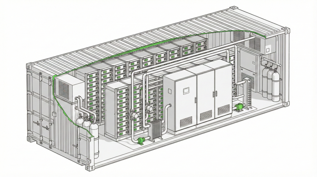
What does this look like in practice? The entire container is very logically and functionally divided:
- On one side — battery modules in rack cabinets
- In another part — PCS and cooling system
- In both sections — fire safety systems
This is not accidental. The entire container is carefully designed — both for safety and servicing, air circulation, cable routing, and system operation in various conditions.
Important: AC-block doesn’t mean you just connect the container with one cable to the grid and you’re done! It all depends on what you’re connecting to what, what voltage you’ll have on the PCS, and what at the connection point.
PCS Efficiency — What the Datasheet Numbers Mean
Manufacturers quote PCS efficiency at 97-98%. But that’s peak efficiency, measured under ideal conditions.
In reality, efficiency depends on:
- Load level (low power = lower efficiency)
- Ambient temperature
- Operating mode (charging vs discharging)
RTE: Declared vs Real Efficiency
Round Trip Efficiency (RTE) is a key economic parameter of energy storage. In simplest terms: how much energy we get out compared to how much we put in.
In offers, we often see 90, 92, sometimes even 95 percent. Sounds great. But the key is where and under what conditions that RTE was calculated.
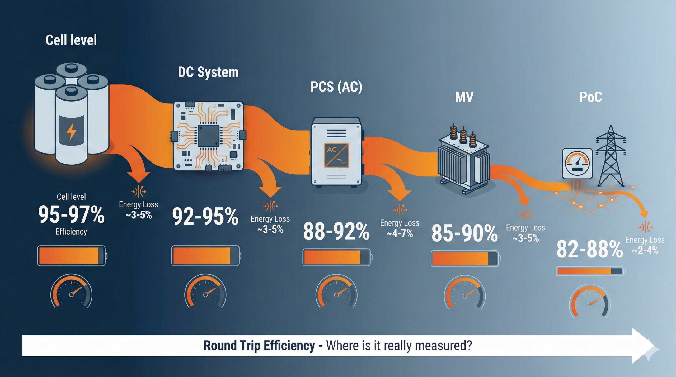
Three Levels of RTE
Manufacturers very often quote RTE of the battery alone or battery with PCS, but without the system’s auxiliary consumption. Meaning without:
- Cooling
- Ventilation
- Control systems
- BMS
- Protections
- Sometimes transformer and switchgear
And these auxiliary loads can be really significant, especially in large containers.
I distinguish three levels:
- RTE of the battery alone
- RTE of the DC-AC system (battery + PCS)
- RTE at the connection point — which is what really matters to the investor
How Much Can These Values Differ?
They can differ by several, sometimes even ten or more percentage points:
- Manufacturer says: RTE 92%
- After adding cooling and auxiliary loads, it comes out to 88-89%
- And if the system operates in difficult conditions — even less
Realistic RTE Values
| Conditions | RTE |
| Datasheet (laboratory conditions, 25°C) | 92-95% |
| New system, optimal conditions | 88-92% |
| System after 5 years, real cycles | 82-88% |
| Extreme conditions (very cold/hot) | 70-80% |
Key principle: 1% difference in RTE means kWh of savings or losses over the entire operating period.
The difference between 85% and 90% RTE with 10 MWh and 300 cycles per year is about 450 MWh of lost energy annually. At a price of €90/MWh — that’s €40,000 difference.
RTE Warranty — Key Negotiation Point
The manufacturer should give you an RTE warranty. And now a very important issue when negotiating the purchase:
- How do we calculate RTE?
- What do we include and what don’t we?
- Where is it measured (at the battery, at the inverter, or at the connection point)?
- What are the contractual penalties for not meeting parameters?
- When do we conduct the annual test and under what conditions?
- Who conducts the tests?
These are exactly the details that determine system operability and what you’re actually paying for.
Cooling Systems: Liquid vs Air
Batteries generate heat during operation. Without proper thermal energy dissipation, cells degrade quickly — or worse, enter thermal runaway.
Air Cooling
Air is cooled and forced circulation removes heat from inside the container. In short — air conditioning.
Advantages:
- Simpler construction
- Lower initial cost (CAPEX)
- Easier maintenance
- No risk of leaks
Disadvantages:
- Lower cooling efficiency
- Uneven heat dissipation (hot spots)
- Higher energy consumption (HVAC)
- Fan noise
- Requires more space
Where it makes sense: smaller systems (up to 1-2 MWh), moderate climate, lower cycling intensity.
Liquid Cooling
Often colloquially called “water cooling.” In practice, it’s not pure water but a mixture of water and polyethylene glycol— very similar to winter windshield washer fluid in cars. Thanks to the glycol, the liquid doesn’t freeze and can operate stably even at low temperatures.
Advantages:
- 4x higher heat capacity of liquid vs air
- Even cooling (temperature difference < 3-4°C in the system)
- Higher energy density (less space for ventilation)
- Quieter operation
- Better performance in extreme temperatures
- Extended battery life by 10-30%
Disadvantages:
- Higher CAPEX
- More complicated maintenance
- Risk of leaks (though minimal with good design)
- Requires periodic fluid replacement
Where it makes sense: utility-scale systems (from 5 MWh), high cycling requirements, extreme climate, limited space.
Polish/Northern European Specifics: Heating is Also Cooling
In Poland and Northern Europe, we have a problem that manufacturers from warmer Asian countries forget about: in winter, batteries need to be heated.
LFP cells lose capacity below 0°C and shouldn’t be charged below -10°C. This means the thermal system must work both ways.
In addition to cooling the cells, we should also cool the PCS and BMS chamber. But in Polish conditions, we also sometimes need to heat these containers! The optimal temperature for cell operation is 20°C. In summer, that’s not a problem, but at -2°C outside — it’s not so obvious anymore.
Anecdote from practice:
We once had a very amusing conversation with one of the suppliers. We asked about container heating, and he replied:
“But the cells heat themselves, so why would you need additional heating?”
And this is exactly the moment where theory meets reality.
Yes — cells do generate heat. But we can’t count on that amount of heat always providing optimal operating conditions for the energy storage system. The storage must operate stably year-round — in winter, in summer, at low load and at full power.
That’s why a professional BESS system should be equipped with both active cooling and heating — to maintain the optimal temperature range, rather than hoping it will “somehow warm itself up.”
Questions for the supplier:
- What is the system’s operating temperature range?
- How much energy does the thermal system consume at -20°C?
- Is heating electric or from a heat pump?
- What is the temperature difference between cells in the system?

Fire Safety: Detection, Suppression, Ventilation
Energy storage fires are a topic that regularly appears in the media. And rightly so — lithium-ion batteries have specific safety requirements.
In Poland, we have no regulations related to energy storage, so as best practice, we should follow proven solutions from the West.
Thermal Runaway — What Is It?
Thermal runaway is an uncontrolled increase in cell temperature caused by chemical reactions inside the battery. It can be triggered by:
- Overcharging
- Mechanical damage
- Internal short circuit
- External overheating
When one cell enters thermal runaway, it can “infect” neighboring cells, leading to a cascade effect.
Layered Approach: Detection + Response + Isolation
The most important thing is a layered approach. Because with batteries, the problem is thermal runaway — if it starts locally, you need to stop the escalation.
Detection Systems
Standard sensors:
- Smoke detectors
- Heat sensors
- Flame detectors
Early Warning:
Not just smoke. Gas sensors, temperature sensors, sometimes multi-point measurements are often more sensible. The earlier you detect, the greater the chance that the system will safely disconnect and a fire won’t develop.
- Li-ion Tamer and similar — detect gases emitted by cells before thermal runaway
- Allow reaction 5-10 minutes before fire
- Increasingly required by insurers
Suppression Agents — What Actually Works?
Novec 1230 (FK-5-1-12):
- Clean agent, doesn’t damage electronics
- Effective on open flames
- Does NOT stop thermal runaway once it has started
- 3M discontinued production in 2025 — alternatives are available (e.g., Fike SF 1230)
Aerosol:
- Interrupts the chain combustion reaction
- Cheap and simple to install
- Doesn’t cool cells
- Requires sealed space
Water Mist:
- Effective cooling
- Can cause short circuits
- Problems with electrical conductivity
- High water consumption
Key truth: No fire suppression system will stop thermal runaway once it has started. When ignition occurs, our goal is not to extinguish the cell (which simply cannot be done), but to limit the spread of fire to other cells and components.
Fire suppression systems prevent fire spread and buy time for evacuation.
Anecdote: For a while, there was an idea to drop burning containers into water tanks located on project sites. Imagine someone driving up with a crane and moving a 40-ton, burning container to a tank 20-30 meters away! Good scenario for a movie — “Speed 6: The Burning Storage”!
Regulatory Requirements
- NFPA 855 — Standard for Energy Storage Systems (USA)
- UL 9540A — Test Method for Thermal Runaway Fire Propagation
- IEC 62933-5-2 — Safety Requirements for Energy Storage (EU)
Questions for the supplier:
- Has the system passed UL 9540A tests?
- What is the detection time from gas emission to alarm?
- Does the system have automatic grid disconnection?
- What is the ventilation for toxic gases after an event?
Supplier Negotiations — The “Cheap Price” Trap
It’s very easy to talk before purchase when negotiating price. When it comes to finalization, suddenly you realize you didn’t account for:
- Higher container durability
- Fire suppression system
- Smoke detection
- Proper cooling/heating
The price you hear at trade shows will certainly be super attractive. When you put it in Excel, suddenly it turns out that energy storage is a golden business — just buy!
But the devil is in the details. In this case — very costly details.
5 Questions You Must Ask Every Supplier
- Cells and Warranty
“Who is the cell manufacturer and what is the degradation warranty? Do you have references from systems operating for more than 5 years?”
Look for: minimum 60% capacity after 6,000 cycles or 15 years. Check if the cell manufacturer has existed long enough to fulfill the warranty.
- RTE at Connection Point
“What is the guaranteed AC-AC RTE after 10 years of operation? What is the auxiliary consumption at 0°C and at 35°C? Is RTE calculated with or without auxiliary loads?”
Look for: RTE > 85% AC-AC at connection point, auxiliary load < 3% of capacity daily.
- Thermal System
“How does the system behave at -20°C? How much energy does heating consume? What is the maximum temperature difference between cells?”
Look for: full functionality down to -30°C, temperature difference < 5°C.
- Safety
“Has the system passed UL 9540A? What is the early thermal runaway detection system? What is the response time? What does detection, suppression, procedures, and service look like?”
Look for: UL 9540A certificate, off-gas detection system, response time < 5 min, references from real commissioning.
- Service and Spare Parts
“What is the availability of spare parts in Europe? What is the guaranteed service response time? Can I use an independent service provider?”
Look for: parts warehouse in the EU, SLA < 24h for critical failures, open service documentation.
Summary
A BESS container is not “a box with batteries” — it’s a complex system where every element affects safety, performance, and investment longevity.
Key takeaways:
- Component hierarchy — from cell through module and rack to container — every level matters
- BMS — protects the investment, even if it sometimes “limits” power
- RTE — the difference between datasheet and reality can cost hundreds of thousands. Only RTE at the connection point, under real operating conditions, matters.
- Cooling — in Poland/Northern Europe, heating in winter is equally important. Don’t count on “cells warming themselves up.”
- Safety — fire suppression systems don’t stop thermal runaway, but they buy time for response
Energy storage is not an off-the-shelf product, but a long-term undertaking. At the beginning, everything looks simple — nice containers, good parameters, attractive prices. But the real difference starts later: in operation, in costs, in market flexibility.
Before making a decision, it’s worth slowing down, calculating everything calmly, and asking the right questions. Because what initially looks like a great opportunity can very quickly turn into a series of technical, formal, and financial problems.
How Can GreenEdge Solutions Help?
Choosing a BESS container supplier is a 15-20 year decision. Don’t base it only on price and datasheet parameters.
Sometimes it’s better to consult with specialists and spend a bit more at the beginning, but save problems you’re not even aware of today — and we’ve already been through them.
GreenEdge Solutions offers support in the procurement process:
🔍 Technical Offer Analysis
- “Apples to apples” parameter comparison
- Verification of compliance with project requirements
- Identification of hidden costs and risks
📋 RFP Preparation and Negotiations
- Technical specification tailored to your needs
- Comparison matrix for offers
- Warranty and service requirements
- Support in negotiating RTE terms and penalties
🏗️ Supplier Due Diligence
- Reference and track record verification
- Service capability assessment
- Financial stability analysis
📊 Delivery and Commissioning Supervision
- Delivery quality control
- Order compliance verification
- Acceptance tests (FAT/SAT)
💰 Profitability Analysis
- We’ll calculate CAPEX, OPEX and provide concrete data
- So you, as investors, can make an informed business decision
Contact us: contact@greenedge-solutions.com
Related Articles
Battery Energy Storage for Manufacturing: When Does BESS Make Sense for Industrial Facilities?
How to Choose an EPC Contractor for Your Battery Storage Project in Poland
BESS Project Development in Poland: Why Most Energy Storage Projects Never Get Built
Listen to the Podcast
🎙️ This article expands on content from Episode 02 of the “Best in BESS” podcast — “What’s Really Inside That Container?”
In the podcast, together with Magdalena Przybylczak, we discuss these topics in an accessible conversational format. Listen on Spotify, Apple Podcasts, or YouTube.